Construction Procedures and Technical Requirements for Underfloor Heating in LOFT Mezzanines
Date:2019-04-08 Views:1652
Construction Procedures and Technical Requirements for Underfloor Heating in LOFT Mezzanines
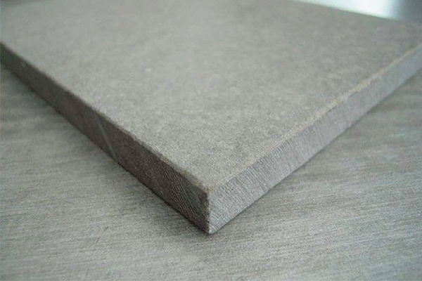
In recent years, a large number of LOFT duplex residential projects have emerged in large and medium-sized cities in northern China. Thanks to their two-story structure and efficient utilization of compact spaces, LOFT apartments have become highly popular among urban young adults. To improve space efficiency and reduce mezzanine thickness, many developers adopt the method of laying fiber cement floor slabs on a steel structure during the construction of LOFT mezzanines.
However, many property owners are puzzled about how to install underfloor heating on the cement slab base of LOFT mezzanines. Based on the structural characteristics of LOFT duplex mezzanines, this article recommends two installation methods for owners to choose from.
Wet Installation
The wet installation method is currently the most mature technology for water-circulating underfloor heating, with a relatively low cost, making it the dominant process in the domestic underfloor heating market.
By definition, wet installation involves embedding underfloor heating pipes in concrete on the LOFT slab base, followed by laying floor finishes such as wood flooring or ceramic tiles over the concrete layer. This concrete layer not only protects and secures the water heating pipes but also serves as the main channel for heat transfer. It ensures uniform heat distribution and minimizes the occurrence of local overheating or underheating.
Construction Procedures
The construction of underfloor heating in LOFT mezzanines using the wet method follows these steps:
Insulation layer installation → Reflective film laying (polyester film or reinforced aluminum foil reflective layer) → Water distribution and collection manifold installation → Underfloor heating pipe laying → First pressure test → Concrete pouring → Second pressure test → Screed and floor finish installation.
The following key points shall be noted during construction:
-
Temporary plugging measures shall be applied to pipe ends when laying heating coils.
-
No pipe fittings shall be installed in the middle of pipes buried under the floor.
-
Before connecting heating pipes to the branches of the manifold, sleeves shall be installed to protect pipes where they penetrate the floor slab.
-
After laying heating coils and before concrete pouring, walking on the pipes with hard-soled shoes, or carrying and stacking materials and equipment on them, is strictly prohibited.
-
Concrete shall only be poured while the heating coils are pressurized at 0.6 MPa. Pressure relief is allowed only after the concrete curing period (normally 48 hours), followed by screed construction and floor finish installation.
Dry Installation
The dry installation method was developed to address the drawbacks of the traditional wet method, including high construction difficulty, long construction period, and difficult maintenance after completion.
Unlike the wet method, which secures water heating pipes with a concrete and pea gravel layer, the dry installation uses specially designed plastic modules. The heating pipes are snapped into the protrusions of these modules, making installation highly convenient. Flooring is then laid directly on the plastic modules, where heat from hot water is transferred to the flooring via air and the modules, which in turn warms the interior space.
Advantages of Dry Module Installation Over Wet Installation
-
In the event of accidental pipe damage during operation, the pipeline can be repaired easily and quickly.
-
It eliminates the need for pipe clips, cable ties, and steel meshes, greatly simplifying construction. With no concrete curing period required, the construction cycle is shortened from one week to just two days.
-
Both the modules and pipes are made of plastic with similar thermal expansion and contraction coefficients, resolving issues such as pipe rupture caused by thermal expansion and cracking of the cement screed.
-
By removing the concrete and pea gravel layer, and integrating the joist layer and heating layer into one plane, the total thickness of the underfloor heating system is only 4.5–5 cm (including a 2 cm insulation layer). This significantly reduces the occupancy of effective floor height, which is particularly critical given the limited vertical space in LOFT duplex apartments.
In comparison, wet installation combined with joists typically requires a 10 cm concrete/pea gravel layer plus a 3 cm joist layer, totaling approximately 13 cm in height.
The dry installation method can be flexibly applied to both joisted and joist-free floors. Wood flooring can be laid directly on the modules, and the system is also compatible with heat storage materials such as thermal insulation sand.
As lightweight plastic components, the modules eliminate the need for cement and pea gravel screeds, reducing material, transportation, and labor costs, as well as the structural load on the floor slab.
Limitations of Dry Installation
Besides a slightly higher cost, the dry method cannot be installed under rigid floor finishes such as ceramic tiles and marble, as these materials require cement for fixing. Therefore, dry installation is generally not suitable for bathrooms and kitchens.
In addition, since the dry installation method was introduced relatively recently in China, its application volume remains lower than that of the wet method. Its adaptability to China’s climatic conditions and interior finishing materials still requires further long-term verification.
Construction Procedures
The dry installation of underfloor heating in LOFT mezzanines follows these steps:
-
Lay insulation materials on the LOFT slab base. The insulation layer shall be flat and tightly jointed. No damage shall be made except for the penetration of plastic clips used to fix the heating pipes.
-
Lay a polyester film or reinforced aluminum foil reflective layer (pre-fabricated or site-installed).
-
Matching and laying of heating pipes:
-
Set out lines according to design drawings (this step can be omitted if lines are pre-printed on the reflective film). Pipe cutting and matching can be omitted if pre-cut to design length.
-
The bending radius of the heating pipe shall not be less than 8 times the outer diameter of the pipe. No joints are allowed within the filling layer, and the heating pipe shall be firmly fixed.
-
The spacing of heating pipe fixing points shall be no more than 700 mm for straight pipes and no more than 350 mm for curved pipes. Five fixing clips shall be installed at each 180° bend.
-
Installation of the heat medium distribution and collection device (manifold):
-
The manifold can be fixed on a wall or in a dedicated box. Generally, the water distribution manifold is installed at the lower position, and the collection manifold at the upper position, with a spacing of 200 mm. The distance from the collection manifold to the finished floor shall not be less than 500 mm.
-
Connection between heating pipes and the manifold:
-
Connections can be made with special clamp-type or compression-type fittings.
-
Thermal insulation sleeves shall be installed at the ends of heating pipes to prevent excessive local floor surface temperature.
-
After firmly connecting the heating pipes to the manifold, flush each circuit one by one until the effluent water is clear.
-
Coordinate with the construction team for the filling layer construction. The system shall be pressurized to no less than 0.6 MPa during this process. Attention shall be paid to expansion joint construction, avoiding extrusion of heating pipes, and proper placement and compaction of pebbled concrete.
The above construction techniques are based on practical experience and are for reference only. For actual construction, property owners shall follow the instructions and standardized operation requirements of design and construction entities.